-
Innowalk is an assistive device that offers full body movement and physical activity for people with moderate to severe disabilities. Innowalk is developed to meet
requirements for use in the home environment.Innowalk is available in three sizes:
Product size User height User weight Innowalk Small 80-125 cm Max. 35 kg Innowalk Medium 120-165 cm Max. 80 kg Innowalk Large 150-200 cm Max. 110 kg Product specifications Width Length Max Height* Weight Innowalk Small 62 cm 158 cm 158 cm 80 kg Innowalk Medium 77 cm 165 cm 206 cm 154 kg Innowalk Large 77 cm 180 cm 230 cm 167 kg *Max height includes max tilt in space, small 11° and medium/large 14°
-
The Innowalk is a medical device intended to be used under the supervision of a qualified healthcare professional, or by trained caregivers or assistants who have received instruction from such a professional or training by a Made for Movement representative. The responsible clinician is solely accountable for assessing the individual suitability, identifying any contraindications, and ensuring correct positioning and adjustment of the device in accordance with the user’s medical condition. All adjustments and settings must be carried out in accordance with the medical or therapeutic prescription.
Any person operating or adjusting the device is required to read the instructions for use thoroughly and strictly follow the recommendations of the responsible clinician.
The manufacturer shall not be held liable for any damage resulting from improper use, disregard of the instructions for use, or deviation from medical recommendations.
User manual - chapter 7.
-
Intended use
The Innowalk is an assistive device for individual use at home under supervision of a trained supervisor, for example a parent or caregiver.Innowalk is an assistive device which enables assisted movement of the lower limbs in a sitting and standing position. The assisted movement of the lower limbs is close to a normal gait pattern with
flexion and extension of hips, knees, and ankle joints.The Innowalk is individually fitted to each user by a Made for Movement representative who has received training to adjust the Innowalk.
Intended use with arm movement (extra equipment)
The Innowalk with arm moving handles is an assistive device for individual use at home under supervision of a trained supervisor, for example a parent or caregiver.Innowalk 2 with arm movement handles enables movement of the lower and upper extremities in a reciprocal pattern in standing position. The assisted movement of the lower limbs is close to a
normal gait pattern with flexion and extension of hips, knees, and ankle joints.The arm movement handles can be swiveled away or removed when not in use.
The Innowalk with arm moving handles is individually fitted to each user by a Made for Movement
representative who has received training to adjust the Innowalk.User manual - chapther 7.
-
Users of the Innowalk have moderate to significant damage to the neuromuscular system and lack movement-related functions of the upper and lower extremities (muscle strength, muscle tone, endurance, coordination, functions of voluntary movements, movement patterns) often with impairment of activities as a result of a brain damage or injury (e.g., cerebral palsy, multiple sclerosis, trauma), spinal cord injury (e.g., paraplegic syndromes due to spinal tumours or trauma) or neuromuscular diseases (e.g., muscular dystrophies).
The user height range is between 80 – 200 cm and body weight limit is 110 kg.User manual - chapter 7.
-
The therapist in charge of the users has the responsibility to assess if the user is a candidate for using the Innowalk. This person is also responsible for evaluating possible risks and side effects against expected benefits of using the device.
Contraindications:
- Bone fractures in lower limbs and/or torso (legs, pelvis, spine)
- Open skin lesions in areas of the body in contact with parts of the Innowalk
Precautions for use:
- Major deformities (spine and lower limbs)
- Severe or fixed contractures in the lower limbs (Hip and knee flexion contractures >40°, pes
equinus >25°) - Osteoporosis with previous or suspected spontaneous fractures of the lower extremities
- Joint instability in the lower limbs (hips, knees, and ankles)
- Circulatory disorders
- Respiratory disorders
- Cardiac disorders
- Epilepsy with uncontrollable grand mal seizures
- Severe spasticity interfering with positioning and movement in the Innowalk
- Pain while in standing weight-bearing position or when moving lower limb
See User manual chapter 7. -
Before the Innowalk is used, the operator must have received training (in accordance with Appendix 1) from a Made for Movement representative to monitor use and provide the user with any necessary assistance. The representative is usually a Made for Movement employee or a distributor / clinician / therapist who is appropriately trained and officially approved to work with the Innowalk.
The training includes a demonstration of all key features, transfers, attachment, safety, use and troubleshooting as described in Appendix 1. In addition, the instructions for use must be read, understood, used and retained for future reference.
User manual - chapther 7.
-
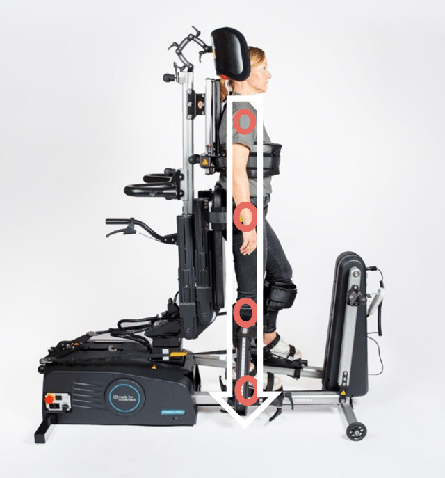
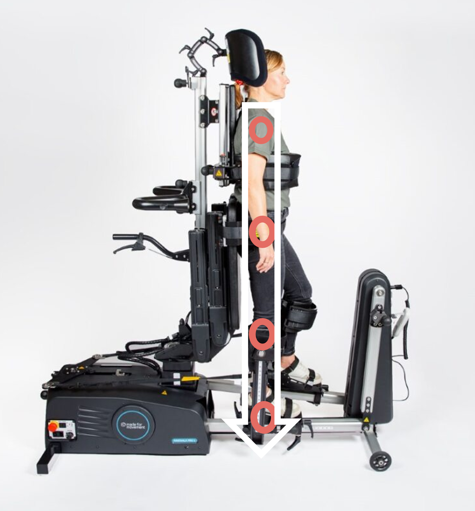
The aim is to optimise the person's position in the Innowalk
- Joint over joint
- Symmetry
Three important support points on the Innowalk
- a. Chest support
- b. Pelvic support
- c. Leg support
Supporting points need to be adjusted to achieve appropriate position in standing.
The goals are to
- Maintain skeletal alignment.
- Facilitate normal movement patterns or control abnormal movement patterns.
The positioning in the Innowalk is dependent on the individual's range of motion in joints, muscle tone/stiffness, upper body control and leg length discrepancy.
Identify and pay attention to:
Range of Motion (ROM)
- Identify range of motion in hips, knees and ankles
- Position in lying is a good indication on what to expect in standing position
- Adjust the device in accordance with limitations in ROM
- Avoid joint stress and ligament overload when positioning the user
Muscle tone/stiffness
- Identify the users muscle tone/stiffness
- Take into considerations muscle tone reaction when the person is being moved
- Adjust device in accordance with limitations related to muscle tone/stiffness. Pay extra attention to the spams control setting
Head and upper body control
- Identify level of control the user has over head and upper body, and asymmetry related to for example scoliosis
- The type of support the user has while sitting in the wheelchair, might be necessary when in standing position too
- Prepare use of for example shoulder straps, tray, front tilt
Leg length discrepancy
- Identify if the user has a leg length discrepancy
- To avoid asymmetry while standing, an extra sole in the foot plate can be used
-

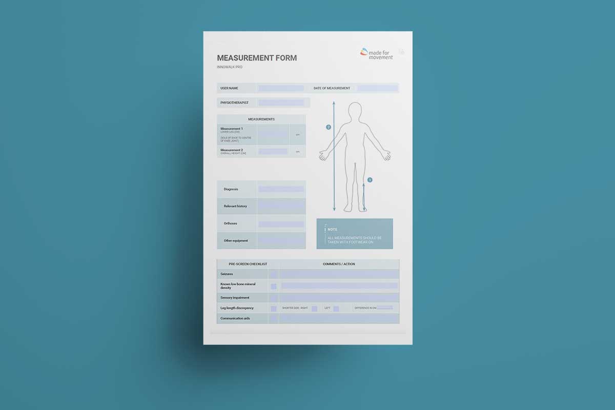
The measurement form can be used during the assessment and before preparing the Innowalk to the user's specifications.
-
All measurements are done with the crank arm at the lowest point (minimum range of movement). If the crank arm is moved to maximum range of motion the measurements for the hip support and chest support increases with about 6 cm for the size Medium and Large.
Small
Min-Max (cm)
Medium
Min-Max (cm)
Large
Min-Max (cm)
Chest width
16-27
22-34
24-38
Hip width
14-28
23-38
29-45
Seat depth (measure from back plate to edge of the seat in front)
Sole of foot to upper edge of the knee padding
21-37
33-50
40-66
Sole of foot to centre of hip support * (in standing position)
31-61
55-90
63-102
Sole of foot to upper edge of the chest* support (in standing position)
56-84
80.5-128
102-145
*Minimum is measured with the seat at minimum height and maximum is measured with seat at maximum height.
-
The Innowalk have integrated transport wheels. The wheels are hidden behind the side covers of the product and are lowered by using the crank arm.
- Ensure the tilt in space function (the front of the Innowalk) is at its loweste position before lowering the transport wheels with the crank.
- Remove the guide straps from the strap hooks before activating the crank.
- Turn the crank handle counterclockwise so that the pully arm moves toward the seat.
- Swing the pully arm so that the wheel hook can be attached to the wheel pin. Make sure that the two green arrows, on the wheel hook and wheel pin, point towards each other.
- Turn the crank handle clockwise until the wheels are lowered to the floor.
- Move and place the Innowalk where it will be used.
- Turn the crank handle counterclockwise to raise the wheels back under the cover and the wheel pin is back to its starting position. The rear legs are now in contact with the floor.
- Release the wheel hook on the pully arm from the wheel pin (by swinging it to the left).
- Turn the crank handle clockwise so that the pully arm returns to its starting position, indicated by the stop screw. The Innowalk is now ready for use.
This is how you transport the Innowalk.
-
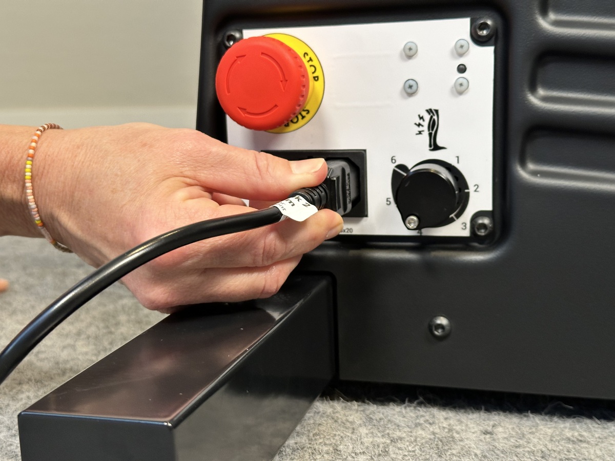
On and off
-

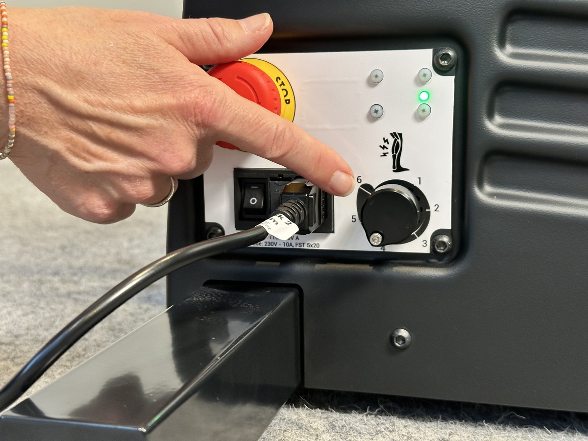
Attach the electrical cable to the product, before connection to the power outlet.
-

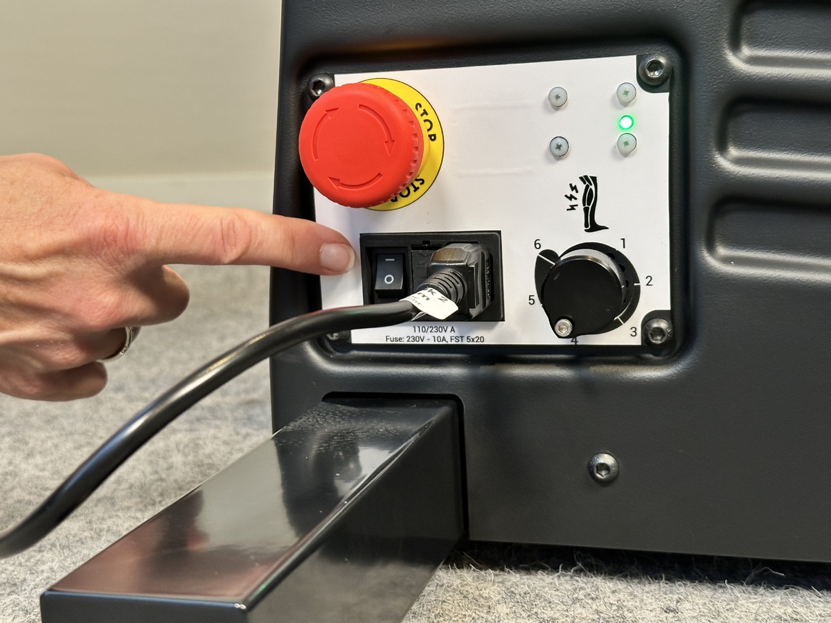
The button is on the side panel. When turned on - WAIT for a long “beep” sound, before you push any buttons. When the device is on and ready to be used the LED on the top right is "Green".
-
-
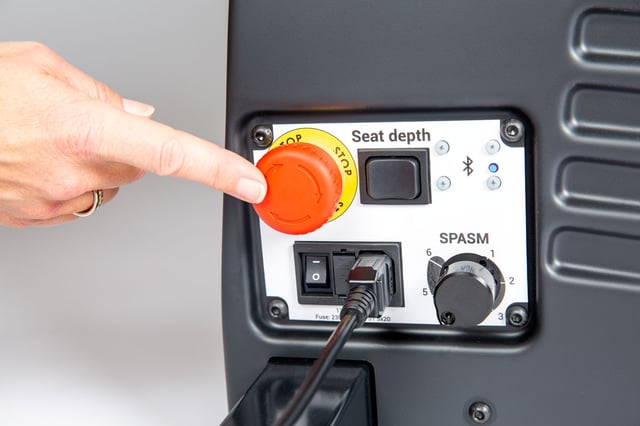
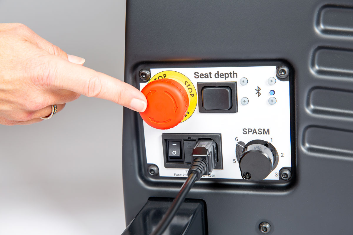
The emergency stop switch is located on the side panel. Push the emergency stop switch to disconnect the power. Rotate the switch to activate the power.
-

The spasm control indicator is located on the side panel. The objective with the spasm control function is to stop the Innowalk if the user has a spasm in the legs.
The spasm resistance level is set individually for each user. If a user has a spasm that exceeds the threshold set, the Innowalk motor will pause. When the spasm is over, the Innowalk will slowly start again.
Adjust the spasm between value 1-6.
1 indicates the lowest level (most sensitive) and 6 the highest level (least sensitive)
At level 1, little force is needed to activate the spasm control and stop the motor and at level 6, a higher force is needed to activate the spasm control and stop the motor.
-
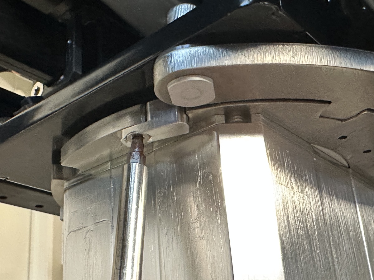
Innowalk size medium and large have an emergency seat lowering mechanism that can be use if the device lose external power or the remote control does not work. The emergency mechanism allow you to manually lower the seat to sitting position.
The emergency release is located at the bottom of the back column. To activate the emergency release, the safety lock on the handle must first be released.
The emergency seat lowering should in normal working conditions not be used.
If the emergency lowering mechanism has been used, there is a need to perform a troubleshooting test to ensure that all functions on the Innowalk are working before the user is entering the device:
- Check that power is on
- Check that the emergency stop switch is not pushed in
- Perform a reset-function called "homing". Press and hold both the “stand” and the “sit” – button on the remote control. While holding you hear one long high pitched beep and you will see the actuator move towards an upright position. When the actuators reach the end position a confirmation beep will sound and you can release the buttons. Homing is now done. When this sequence is finished, the sit to stand function should react normally to input on the remote control.
- Check that the device respond to all other functions on the remote control.
If the device is not responding as intended, please contact your Made for Movement representative and report failure.
-
Seat and upright actuator homing
If the sit to stand function doesn’t respond to the remote control, a reset-function called “homing” must be performed.
Warning: Never perform “homing” with the user in the device.
- Power on the device.
- Simultaneously press and hold the "Stand" and "Sit" buttons. You will hear a short beep and after approx. 8 seconds you will hear a longer high pitch beep and the unit will begin to engage in standing, keep holding the sit to stand buttons.
- When the homing is complete you will hear a short confirmation beep. Now you can release the buttons. Homing is completed.
- When this sequence is finished, the sit to stand function should react normally to input on the remote control.
Seat height actuator homing (size M & L)
If the seat height function doesn’t respond to the remote control, a reset-function called “homing” must be performed.
Warning: Never perform “homing” with the user in the device.
- Power on the device.
- Simultaneously press and hold the "Seat up" and "Seat down" buttons. You will hear a short beep and after approx. 8 seconds you will hear a longer high pitch beep and the unit will begin to engage in raising, keep holding the "seat up" & "seat down" buttons
- When the homing is complete you will hear a short confirmation beep. Now you can release the buttons. Homing completed.
- When this sequence is finished, the seat height function should react normally to input on the remote control.
-
The seat on the Innowalk can be turned to either the left or the right side, for easier transfer in and out.
Swivel seat size S
Pull the index bolt up and turn the seat to the side (left or right).
Swivel seat size M & L
Pull down and turn the index bolt under the front of the seat to the side to release the locking mechanism for the swivel seat.
Rotate the seat using your other hand.

Optional 45° lock
The standard swivel seat position at delivery is 90°. If it is more convenient for the user to enter the device with the seat at a 45° angle, remove the small aluminum bracket located underneath the seat. If a 45° lock is required when rotating the seat both to the left and to the right, remove both brackets under the seat.
-
Swing out the upper part of the leg support by pulling the index bolt - lift the leg support upwards and rotate it.
Release the bolt at the back to fold the leg support all the way down parallel to the ski.
-
The front tilt function allows for a reclined sitting and/or standing position. The tilt function can be used if a user presents with limited upper body and head control.
Front tilt up/down botton is positioned on the front of the device.
Tilt in space is 11° for size S and 14° for size M/L.
A measurment scale is available on the front-side (M/L) and front (S).
-
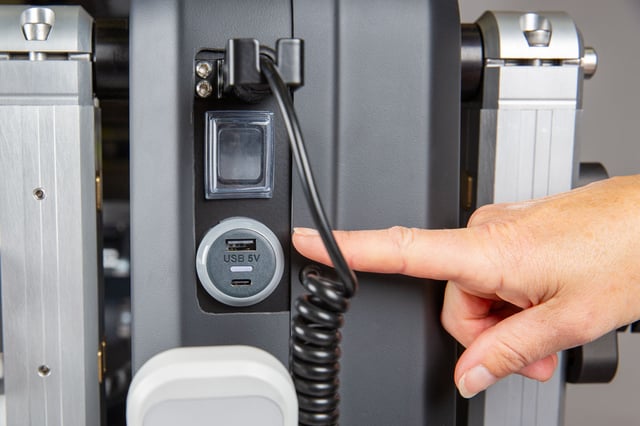
A USB charger is available on the size M & L at the front of the Innowalk. It can be used to charge handheld devices e.g. a tablet or phone.
-
Increase and decrease seat depth
To adjust the seat depth on the Innowalk (size Small), loosen and remove all four screws on the two bars beneath the seat. Set the seat to the desired depth, then reinsert and securely tighten all four screws.
-
Increase seat depth
Loosen the two screws on the upper parallel arms beneath the seat on both sides. Pull the column backwards to increase the seat depth, position it as desired, and tighten the four screws securely.
Next, loosen the two screws on the lower parallel arms on both sides and push the column forwards. Use the scale to ensure it aligns correctly with the position set on the upper arms. Finally, tighten all four screws securely.
Decrease seat depth
To decrease seat depth, loosen the two screws on the the lower parallel arms on both sides. Pull the column backwards to decrease the seath depth. Position it as desired, and thighten all four screwes securely.
Next, loosen the two screws on the upper parallel arms on both sides and push the coumn forwards. Use the scale to senure it aligns correctly with the position set on the lower arms. Finally, tighten all four screws securely.
-
The Innowalk size M is delivered with a seat extension plate and a seat extension pillow. These parts must be removed if the seat depth is to be adjusted from position 5 inwards (positions 1 to 5).
-
Seat height size S
The seat height on the Innowalk small is adjusted using the foot plate scissor mechanism.
Loosen all screws and set the foot plate to the desired height. Tighten the middle screw to secure the height, then tighten remaining screws.
-
Seat height size M & L
The Innowalk size M and L models feature an electric seat height adjustment. Use the seat height indicator on the remote control to set the desired height.
A remote blind cover (art.no 304921) can be fitted over the seat height controls to prevent unintentional adjustments.
-
Lengthweise position - size S
The foot plates can be adjusted lengthwise.
Loosen the front and back screws on the side of the foot plate and adjust it back and forward.
Tighten both screws when the foot plate is at desired position.
Use a measuring tape to replicate the footplate position on the opposite side. Identify a consistent reference point to measure from.
Lengthwise position - size M/L
The foot plates can be adjusted lengthwise.
Loosen the screws under the foot plate and adjust it back and forward.
Tighten all screws when the foot plate is at desired position.
The aim is to position the foot plates in a position where the user is aligned with hips over knees and knees over ankles in standing position.
Use a measuring tape to replicate the footplate position on the opposite side. Identify a consistent reference point to measure from.
Sideway position
The footplates can be adjusted sideways.
Adjust the width of feet position by loosening the screws on the footplate. Two in the front and two at the back.
Replicate desired position to the other side.
-
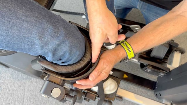
Leg support height
Loosen the screw on the side of the leg support
Use the adjustment dial at the from of the leg support to adjust the height.
Adjust the height of the leg support so the upper part of the padding is approximately 1 cm under the patella.
Choose the standard support padding (thin) or the thick padding.

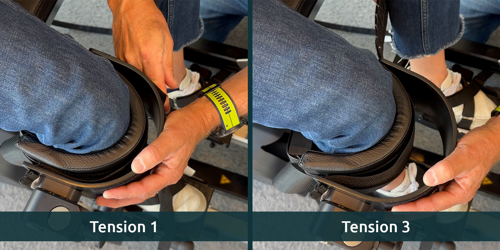
Leg support padding strap tension
Make sure the Velcro on the knee support is properly aligned for correct positioning.
Start with tension level 1 as the standard setting. To move the knee further back in the calf bow, adjust to tension levels 2 or 3.
The centre of the knee should align with the centre of the leg support attachment point.
-
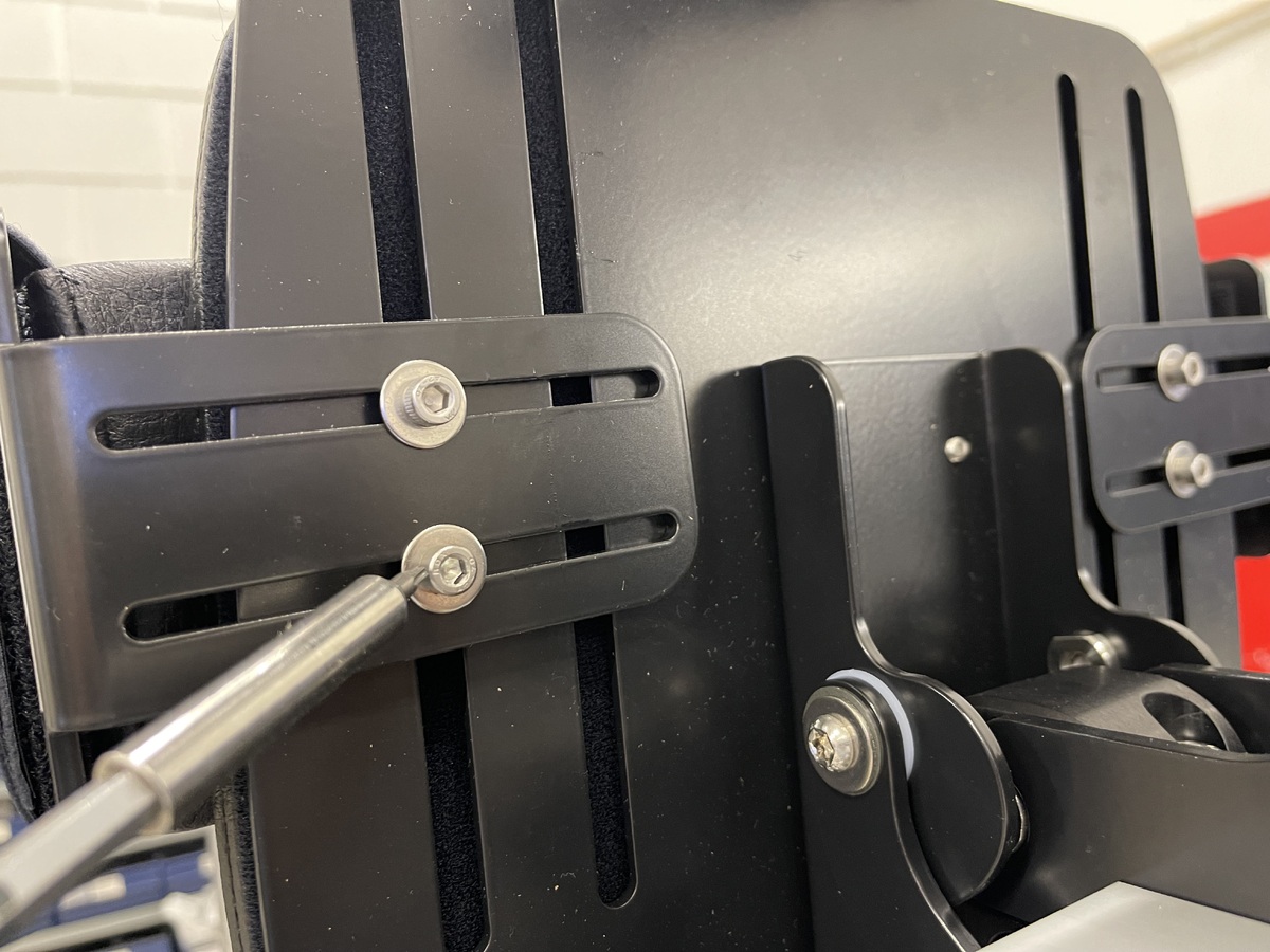
To adjust the height of the chest support on the back column, loosen the screw and slide the support to the desired position. Repeat the process on the opposite side.
To adjust the width of the chest support, loosen the screw on the side of each support and slide it to the desired position. Tighten the screws securely once both sides are adjusted.
-
Use one adjustment dial to change both the height and width of chest support.
Height - align the top of the bracket with the the measurement scale.
Width - align the middel of the adjustment dial to the measurement scale. -

Adjust width and height of the hip support by loosening the two screws.
-
The hip support can be adjusted in height and width.
Adjust Width: Use the middle wingnut
Adjust Height: Loosen the two screws -
Height - release the dial to adjust height of the head rest.
Angle - loosen the two screws to adjust the angle of the headrest.
-
Height - release the dial to adjust height of the headrest
Angle - release the wingnuts to adjust angle of the headrest.
-
Attach the guide-strap
Attach the guide-strap to the hock on the leg support on both sides, before adjusting the length of the guide-strap.
Warning: Never bring a user into standing without attaching guide-straps to both sides.
Length of guide-strap
The position of the leg support is adjusted by the length of the guide-strap.
To provide an optimal position of user, define the desired length on the guide-strap.
The guide-strap length is adjusted by using the crank-handle at the back of the device.
Clockwise turning – to shorten the guide-strap.
Anti-clockwise turning – to lengthen the guide-strap.

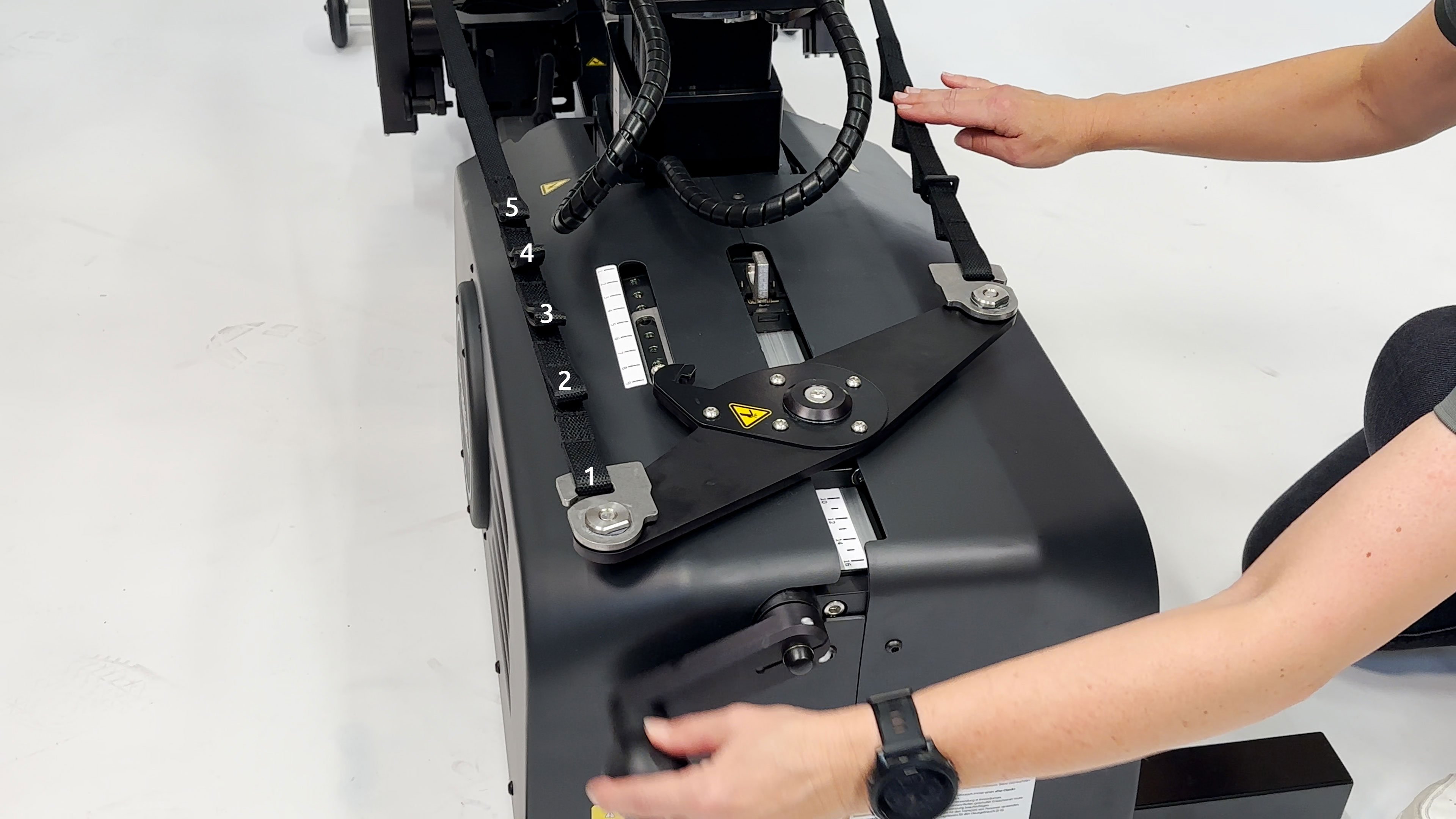
Guide-strap loops
In most cases the length of the guide-strap is handled by using the crank-handle. In cases where there is a need to shorten the guide-strap further, the loops on the guide-strap can be used.
There are 5 loops. Standard is loop nr. 1.
-
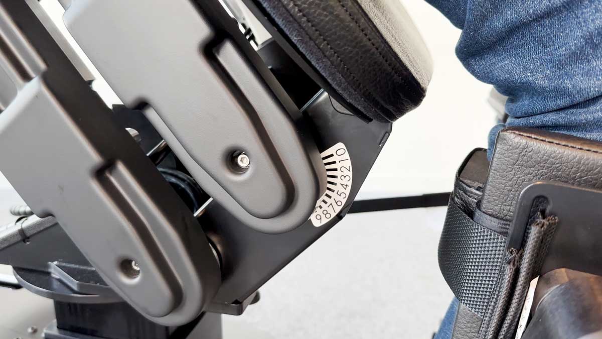
The cam stop, located parallel to the foot plate, reduces the range of motion of the leg support and may be used to reduce hyperextension at the knee.
Relase the bolt to adjust the screw:
Clockwise turning of the screw- Cam stop moves toward leg support to reduce knee extension.
Anti-clockwise turning of the screw - Cam stop moves away from leg support, allowing knee extension.
Remember to tighten en bolt when the camstop is at the desired position.
-

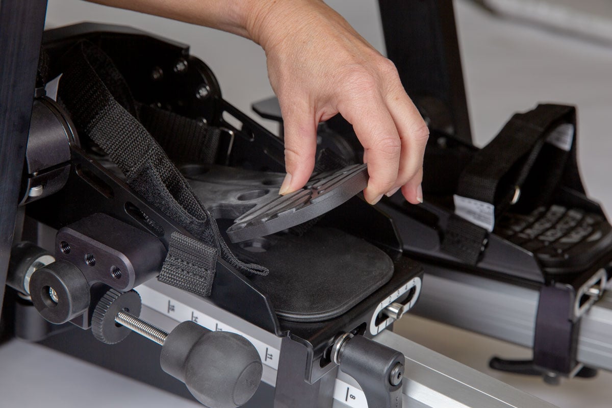
Insert the extra sole to compensate for leg length discrepancy, if needed.
One sole is 1 cm. You can stack up 2 cm.

-
The tray can be swiveled away or removed when it is not in use.
Attach the tray by entering the tube-bracket. Pull down the knob and swivel the tray to front position. Pull down the knob to swivel the tray away.
Adjust the height of the tray by releasing the knob at the back of the column. Slide the tray up/down to the desired position and tighten the knob again.
Depth and angle of the tray is adjusted by loosening the adjustment knobs under the tray.
The tray can be assembled so that it can swing either to the right or to the left side.
Product Art.no. Innowalk small tray 302738 Innowalk medium tray 304469 Innowalk large tray 304470 -
Attach the bracket for the shoulder straps to the column. The top end of the straps inserts through the bracket on the column and the bottom end of the straps inserts through the receivers attached to the chest belt. Adjust the length of the straps, so it supports the user well in standing.
Product Art. no. Shoulder straps w/bracket Innowalk Small 303327 Shoulder straps w/bracket Innowalk Medium 303328 Shoulder straps w/bracket Innowalk Large 303329 -

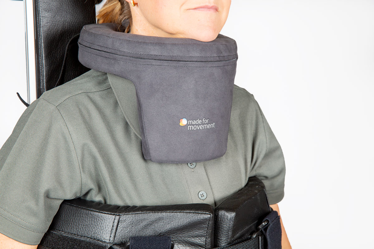
The Neck collar can be used if the user has limited head control. It is available in 3 sizes:
Neck circumference
- S: 30 cm (+/- 5 cm)
-
M: 40 cm (+/- 5 cm)
-
L: 50 cm (+/- 5 cm)
Product Art. no. Neck collar size S 105067 Neck collar size M 105066 Neck collar size L 105065 -
There is two versions of the arm movement handles:
- Standard without joints
- Pro versjon with joints
Height adjustment (standard and Pro version):
- Attach the arm handles in the brackets and adjust to desired height
Angle adjustment (Pro version only):
- Position the handles by releasing the two knobs. A scale on the joints can be used for positioning. Ensure when tightening the knobs, that the locking joints are interlacing.
Product Art. no. Arm movement handles Innowalk Small 302741 Arm movement handles Innowalk Medium/Large 302742 Arm movement handles Innowalk Pro 304473 -

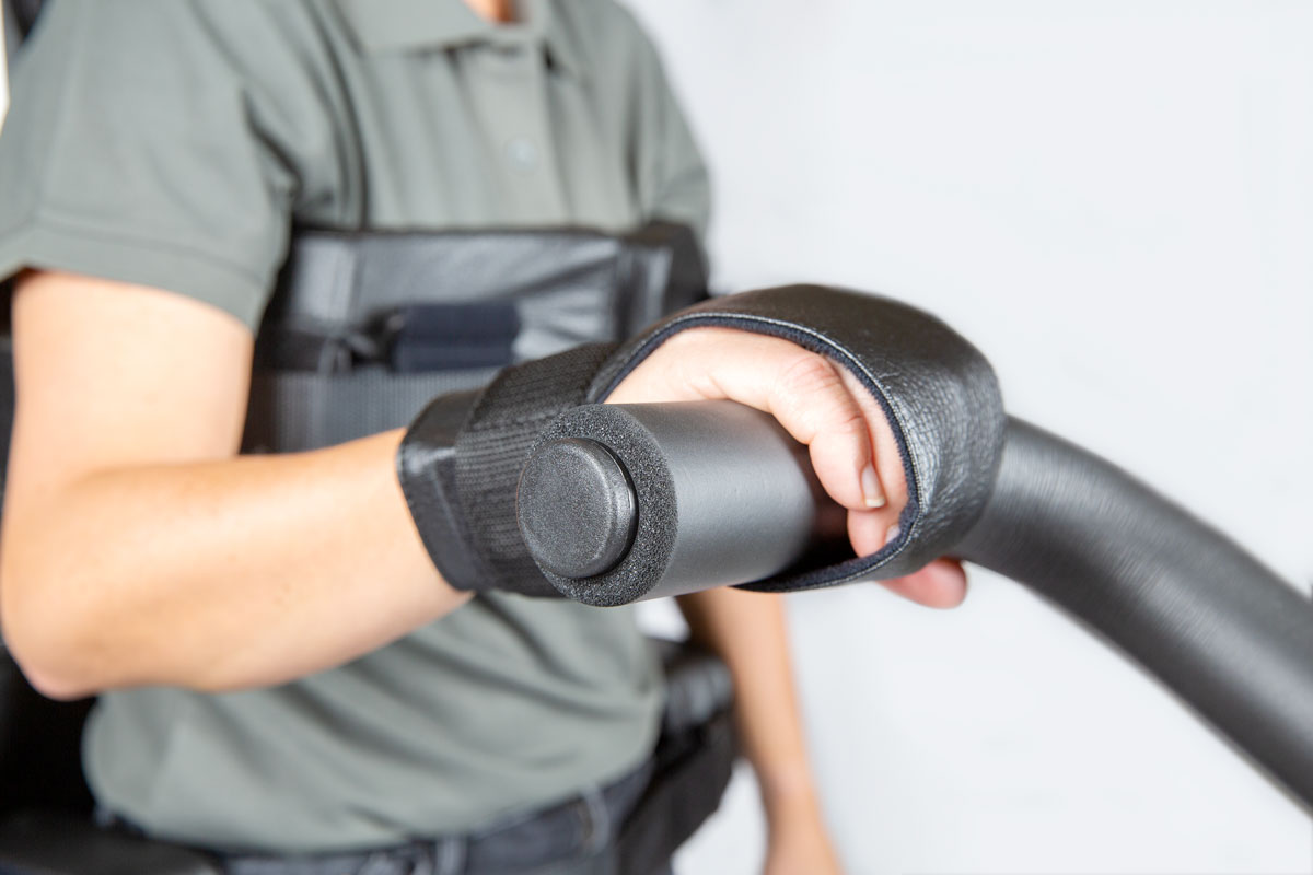
Hand fixation gloves can be used in combination with the arm handles to support positioning of the hands.
Product Art. no. Hand fixation glove small LEFT 300405 Hand fixation glove small RIGHT 300404 Hand fixation glove medium LEFT 301366 Hand fixation glove medium RIGHT 301365 Hand fixation glove large LEFT 301368 Hand fixation glove large RIGHT 301367 -
The build up soles can be placed on the footplates to compensate for leg length discrepancy up to 2 cm.
Shoe build up brackets can be used under the foot plates for extended build up in height. These two options is only for Innwowalk size M/L.
Product Art. no. Shoe build up sole 10mm Innowalk M/L - Right 300314 Shoe build up sole 10mm Innowalk M/L - Left 300313 Shoe build up kit 30mm Innowalk M/L 303330 Shoe build up kit 50mm Innowalk M/L 303331 -
The body plate provides additional support in the device and is suitable for individuals with limited control of the lower trunk.
Fasten the bracket to the column of the Innowalk and attach the body plate straps to the bracket. The bracket can be moved up or down to achieve the correct positioning. The tightness of the body plate is adjusted using the Velcro.

Product Art. no. Body plate incl. bracket 304847 -
A tablet holder with a flexible arm is available for the Innowalk. It is mounted on the front tilt and uses spring-loaded clamps to secure the tablet. The flexible arm, together with the ball joint at the top, allows for easy positioning, tilting, and rotation.
Product Art. no. Gooseneck tablet holder 304849 -
Challenge:
The chest support may be positioned too high for the smallest users.Solution:
Add height by stacking soles on the footplate. One sole is included in the standard configuration and provides a 0.5 cm lift.If additional height is needed, order the “Innowalk 2 Small Kit for users around 80 cm”, which includes:
- six soles
Product Art. no. Innowalk 2 Small kit for user size around 80 cm 304982 -
Challenge:
The hip support and seat may be too shallow.Solution:
Upgrade to a larger hip support size, along with a seat plate and padding with increased depth.Order the “Innowalk 2 Small Kit for users above 110 cm”, which includes:
- extended seat plate
- extended seat padding
- IW2 Medium hip support.
Product Art. no. Innowalk 2 Small kit for users above 110 cm 304983 -
Challenge:
For users in the lower size range and/or with a slim build, the chest support may be too large and positioned too high.Solution:
Switch to the smaller chest padding (Innowalk 2 Small) and add soles to the footplates to increase the user’s effective height.
The standard configuration includes one pair of soles.For additional adjustment, order the “Innowalk 2 Medium Kit for users between 120–125 cm”, which includes:
- small chest padding (left and right)
- four soles (10 mm shoe build-up, left and right). This allows you to increase the user’s height by up to 3 cm.
Product Art. no. Innowalk 2 Med kit for user between 120-125 cm 304984 -
Challenge:
The chest support and hip support are too small.Solution:
Upgrade to larger chest padding and a larger hip support (note the potential conflict between the chest and hip supports when in a seated position).Order the “Innowalk 2 Medium Kit for users within the size range but with increased body mass”, which includes:
- IW2 Large chest padding (left and right)
- IW2 Large chest belt
- IW2 Large hip support
Product Art. no. Innowalk 2 Med kit for user within size range, but increased body mass 304985
-

The Innowalk activity tracker allow you to record session data:
- Speed, time, distance
- Standing position - seat angle
- Results displayed in easy-to-read charts

1. Download app
Search for “Innowalk Activity Tracker” in the App Store or Google Play and download the app.
Note:
The app only connects to Innowalk devices with Bluetooth, which includes products with the following serial numbers:IW 2 Small: from serial number IW2S-10055 and onwards
IW 2 Medium: from serial number IW2M-10116 and onwards
IW 2 Large: from serial number IW2L-10093 and onwards2. Register
Fill in details to create an account and consent t the mandatory fields in terms an conditions.
Under "Change data" in the app you can "Delete account". Be aware that if you "Delete account" all sessions will be deleted and can not be recovered in any way.
3. Connect the Innowalk
Open the app and connect to your Innowalk via Bluetooth.
4. Registering a Session
To start recording a session:
- Open the app
- Go to "view all sessions"
- Tap the “+” button
- Begin the session
-
Before transferring the user into the device:
- Turn on the device
- Place the Innowalk in sitting position
- Swing away the leg supports
- Open all straps, chest and hip support, release the guide-straps
- Position foot plate on the entrance side in lowest position in the walking cycle
- Turn swivel seat to preferred entrance side (if used)
-
Transfer
Transfer the user into the seat. In the sitting position using the swivel seat the person's feet should be on the ground to increase stability. Support the user carefully, until you have secured the chest support and belt.
The person can also be transferred into the device with a hoist, without using the swivel seat function.
Turn swivel seat to front position
Increase the sitting height before turning the seat to front position. This will allow for easier access of the users feet to locate into the foot plates.
Secure straps over the feet
Make sure the users heels is in contact with the heel cap on the foot plate. Secure the straps over the feet. Make sure the straps are tight enough to avoid the person from moving the feet that may result into an incorrect position.
Attach leg support and guide-string
Attach the leg support to the user and secure the strap. You can adjust the users leg position back and forward in the leg support by adjusting the strap on the upholstery padding.
Attach the guide-string on the hook on the leg support on both sides and adjust the length on the guide-string with the crank handle at the back.
Sitting to standing position
Use the remote control to move the user from a sitting to standing position. To ensure good alignment in standing an operator can push down on the guide-strap when transitioning from sitting into standing. Reduce the tension on the guide-strap gradually when the person is standing in the desired position.
The grade indicator can be used to define individual amount of stretch position.
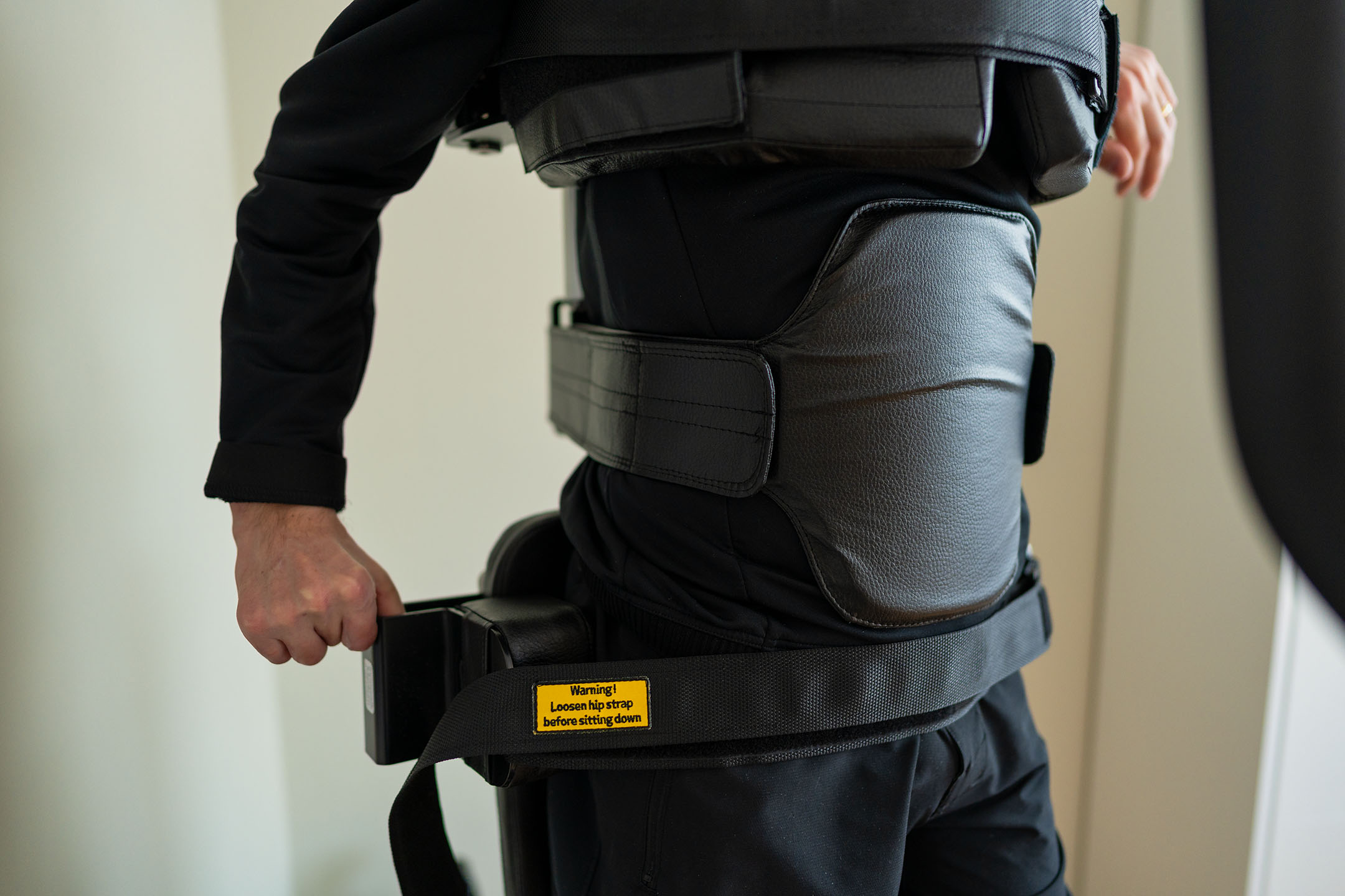
Secure the hip belt
Adjust the hip supports into the desired position (at the level of Trochanter major) and secure the hip belt.
-
Release hip belt
Always release the hip belt in standing, before lowering the user down into sitting position.
Lower the device into sitting position
Use the remote control to lower the user into a sitting position. An operator can put pressure on the guide-strap to avoid the person from sliding down on the seat during the transition process.
Release the leg support
Release the straps over the feet. Unhook the guide-straps, release the leg supports and swing them away.
Turn seat to side position
Increase the seat height to release the feet from the foot plates. Turn the swivel seat to side position desired for preferred exit. Pay attention to user's legs when rotating the seat, so they don't get tangled. Lower the seat down, so the person's feet are in good contact with the floor.
Release the chest support
Support the person, when you release the chest belt and support. You can now transfer the person safely out of the device.
A hoist can also be used to transfer the person out of the device. Ensure slings and hoists are securely attached and in position before releasing the chest supports.
-
Possible solutions
- Use the tilt function to recline the Innowalk. This can help the user balance the head and trunk.
- Use the shoulder straps for support.
- Attach the tray table in the preferred height in front of the user. Let the user support the underarms on the table. This can encourage a more upright position of the head and trunk
- Use neck support in the right size fitting the user to support the head
- All mention solutions can be used separately or combined.
- Use the tilt function to recline the Innowalk. This can help the user balance the head and trunk.
-
Possible solutions
- Position the foot plates forward on the skis to compensate for reduced ROM in the ankles. The user’s lateral malleolus should be a few centimetres in front of the knee joint when the foot is in the lowest position. Adjust the footplates symmetrically.
- When adjusting the foot plates forward, bear in mind, that there is a need to increase length on the guide-strap. Adjust the length of the guide-strap in accordance to position of the legs.
- Observe the position and the movement of the ankle when the use is in standing and in movement
- If the user is lifting the heel up while moving there is a need to move the foot plates increasingly more forward
NOTE! Do not tighten the front strap over the foot when using fixed orthoses, as no plantar or dorsiflexion will be possible.
- Position the foot plates forward on the skis to compensate for reduced ROM in the ankles. The user’s lateral malleolus should be a few centimetres in front of the knee joint when the foot is in the lowest position. Adjust the footplates symmetrically.
-

Due to reduced ROM in knees and hips, it may not be possible to achieve full extension in standing. There is a need to allow the user to be in a midway position of sitting/standing.
Possible solutions
- Measure the extension deficit in knees and hips before testing out the Innowalk, to know how much the user can extend into a standing position.
- Have the user’s most affected leg in the lowest position in the Innowalk while seated.
- NOTE! The guide-strap should be tight when sitting.
- Observe closely the user’s most affected knee when moving from sitting to standing position.
- STOP in the position according to ROM in knees and hips (a goniometer over the knee joint can be used to control ROM). The position indicator ruler on the seat can be used as a reference value for future sessions.
- Solution described in FAQ 2 can also be used.
-

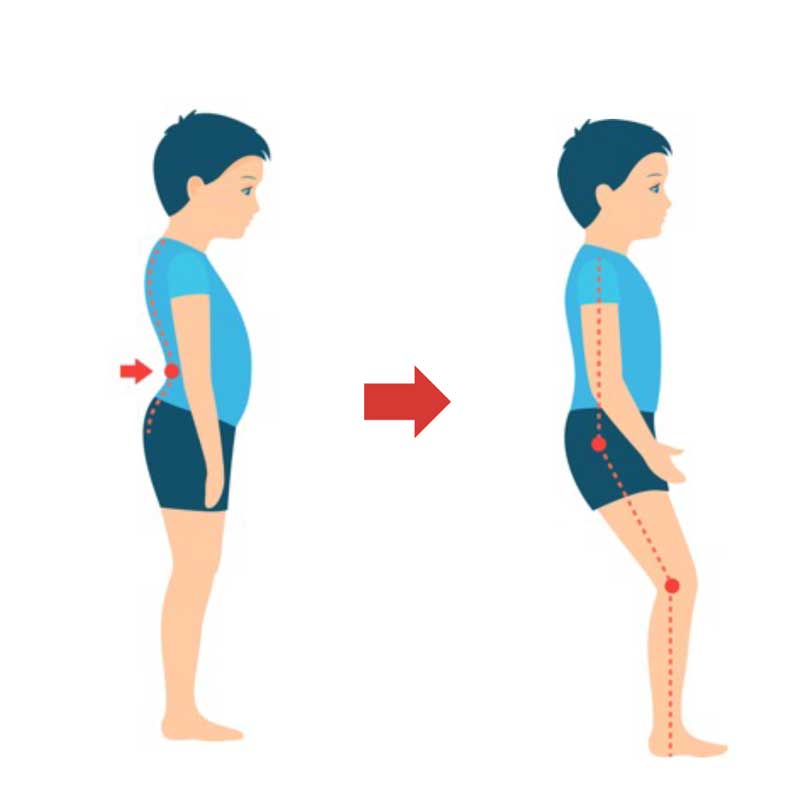
When moving the user into full stretch in standing the user will compensate with “anteversion” of the pelvis if he/she has an extension deficit in the hips.
Possible solution
- To avoid compensating movement of the pelvis move the seat on the Innowalk down a little into increased sitting position, by pressing the «down button» 1-2 times on the remote control. This will allow for some flexion over the hips
- Observe that the user’s pelvis is in a natural position
- Shorten the length on the guide-strap if more stretch over the knees is available & desired
-
Possible solution
- Measure the leg length discrepancy and use the extra build up sole inserts supplied on the shortest leg (compensate up to 2 cm difference).
- Observe the movement when the patient is standing to make sure that the movement is symmetrical. If the patient is overstretching on the leg, please see FAQ 6.
- Measure the leg length discrepancy and use the extra build up sole inserts supplied on the shortest leg (compensate up to 2 cm difference).
-

Possible solutions
- Ensure that all settings on the Innowalk are symmetrical and that the user is positioned symmetrically
- Control the length on the guide-strap. Is the guide-strap too short and causing the extension pattern? Lengthen the guide-strap.
If it is not the guide-strap causing the extension pattern, the user might need to have some flexion over the hips to “control the spasticity”.
- Move the seat on the Innowalk down a little into increases sitting position, by pressing the «down button» 1-2 times on the remote control
- Or use the cam stop/anti-overstretch to reduce extension over the knees
-
Possible solutions
- Check the position of the leg support – is it too high/low?
- Check the distance between the foot plates. If the user is standing with too much of a width stance, the pressure will increase on the medial side of the knee
- Check the upholstery padding– is it positioned correctly?
- Check the position of the leg support – is it too high/low?
-
Possible solutions
- Ensure that the hip supports are symmetrical in height and width.
- Check that the all settings on the footplates/ski’s are symmetrical.
- Check for leg length discrepancy.
- Check ROM of the knees, do they differ from each other? Adjust in accordance to the leg with decreased ROM (FAQ 2), or use the cam stop (FAQ 6), to achieve symmetrical position.
- In case of pelvic rotation that is not related to any of the above-mentioned adjustments or leg discrepancy. Stop the movement of the legs and align the position of the user/patient and tighten the hip belt for better support.
- Ensure that the hip supports are symmetrical in height and width.
-
Possible solution
In most cases this is caused by too long sitting depth. It is recommended to decrease sitting depth to reduce the movement of the chest support from sitting to standing.
-
AFO’s can be used in the Innowalk, but you should be aware of the limitations in range of motion in the ankle joint this might cause. To compensate for this, adjustments are needed on the footplates and the length of the guide-strap.
For details on adjustments see FAQ 2.
-
In most cases when the user is allowed to weight-bear, move in a gait like pattern and is pain free when standing, the Innowalk can be used.
Nevertheless, it is recommended to discuss potential contraindications and precautions with the physician before use.
Always pay close attention to the user during movement in the device and in case of any negative reaction the session should be stopped.

-
The cover has the function to block the buttons that controls the sitting height of the user.
To attach the cover, slide it over the remote from the top.
To remove the cover, slightly lift the tab from behind the remote, and pull upwards.
-
1. Remove rear beam
Engage the transport solution and rise to max height. Loosen and remove the two M10 screws at the back of the device using a Unbrako 8mm key. Be carefull when removing the last screw as the rear beam will drop down.
2. Attach rear beam
Position the rear beam and enter the two M10 screws loosly so the rear beam will not fall down. Now tighten the screws with the Unbrako 8mm firmly. Causion: If the screws has much ressistance when entering, make sure it entered correctly. It shall rotate with little ressistance.
-
This video demonstrates the procedure for changing the stride length of the Innowalk 2 in sizes S, M, and L and Pro models.
-
1. Remove cover
Remove the round covers using a 3mm Unbrako key.
2. Inspection of belts
Inspect the belts during movement and look for skipping og jumping. IMPORTANT: Keep away from moving parts during inspection. Serious squeeze hazzard.
3. Inspect slack
Unplug the device and feel for slack on the belts. 8-15mm slack is to much.
4. Tighten belt right side
Use a 8mm Unbrako key. Loosen the screw holding the right side tighten belt. Apply force by hand to tighten the belt and then thighten the screw to keep the belt in place. You migth need to hold it tight while fastening the screw.
5. Tighten belt left side
Do the same on the left side of the device. Here it needs to be used a thin screwdriver or other tool to tighten the pulley. With force applied, tighten the screw.
6. Control tension of belts
Before plugging in the device, control the tension on both belts. 4-6mm is accepted. Remove hands and plug in the device and start the motor. Visually control that the skipping and jumping of the belt is gone.
7. Attach cover
Reattach the round covers with the 3mm Unbrako.
-
1. Loosen lock pin
Use a flat head screw driver or similar tool to bend out the lock pin fron the large locking nut. Use hammer if needed. Carefull with the surrounding components.
2. Tighten lock nut
Use a mandrel og punch to tighten the lock nut to the next avalible lock ring plate. Allign the pin with the plate.
3. Tighten lock pin
Bend and tap the lock pin into the groove on the locking nut. Use a hammer and a mandrel to do this. Do not tap it all the way in as this makes it hard to adjust it again later if needed.
-
How to assemble the emergency safety pin on the emergency lowering handle.
How to use the emergency lowering function, please see under "Use & adjustments" - "Emergency release - size M/L".
-
Video explaining how to asemble the phone and tablet holder on the Innowalk.
-
1. Remove cover
Use a 4mm Unbrako bit or key to remove all screws on both side covers. Remove the left side cover (seen from behind the product).
2. Disconnect wires left side
Disconnect all the wires carefully on the left side of the electro box. CAUSION: Do not pull on the wires, only the connector.
3. Disconnect wires right side
Carefully flip the right side cover to its side. Use a star bit to loosen the screw on the emergency stop and remove the red wire connected to the electro box. Then carefully wiggle the black wire out from the power inlet. Now carefully disconnect all the contacts from the right side of the electro box. CAUSION: Do not pull on the wires, only the connector.
4. Remove screws
Using a flat head screwdriver remove the four plastic screws that holds the electro box.
5. Remove electro box
Move the pulley all the way forward using the crank handle. Carefully angle the electro box as seen on the video to remove it from the frame.
6. Insert new electro box
Insert the new electrobox in an angle as shown in the video. Make sure that no wires are clamped under the electro box on both sides.
7. Attach new electro box
Attach the electro box using the four plastic screws. CAUSION: do not overtighten. Only tighten until the black pads on the electro box are touching the rear frame. The back of the electro box shall not bend notably against the screws.
8. Attach wires right side
Connect the four connectors on the right side. Pay close attention to the video for correct placement. CAUSION: The connector shall not have any ressitance when entered propely into the electro box. If this is the case make sure the locking clip in the connector is oriented correctly and you are in line with the socket.
9. Attach wires from side cover - right side (1)
Place the right side cover as shown in the video. Flip it onto its side and first connect the black wire to the power inlet. This might take some force to properly put in place. Insert the red wire into the emergency stop and thighten firmly with the star bit. Pull on the wire to make sure its properly in place. Conform also again that the black wire is properly in place.
10. Atttach wires from side cover - right side (2)
Connect the remaning connectors from the control panel into the electro box. Pay close attension to the placement of the connectors on the electro box. Some of the wires are labeled. CAUSION: The connector shall not have any ressitance when entered propely into the electro box. If this is the case make sure the locking clip in the connector is oriented correctly and you are in line with the socket.
11. Attach wires left side
Do the same on the left side of the electro box. Carefully compare the wires in front of you and replicate the video. If you are unsure, look at where the wire are comming from (indicated in the video). The black RJ45 cables are labeled and can be compared with the on screen image. The connectors are will have a bit more ressitance, but if you are struggeling to insert a connector be sure allignment and orientation is correct. IMPORTANT: Be sure that the wires can not come in conflict witht moving parts of the drive!
12. Test before final assembly
Flip the side cover upright, and insert the power cable. Run a test of all functions to ensure that the replacement was succesful before assembling the covers.
13. Reassemble covers
Now reassemble the covers using the 4mm Unbrako bit/key. Note left side cover: Be sure to place the wires for the seat and upright into its slot. Positioning the cover correctly in the rear takes some force.
-
1. Remove covers
Rise the "seat and upright" to approximatly 45°. Remove the 8 screws with a Unbrako 4mm bit or key. Carefully remove the covers (this can be a bit difficult). Carefull with the wires and contatcs. .
2. Manually homing
If the back support are out of sync, manually in increments, twist so the back support ends in its inner position. It is in its end position when all the four yellow LEDs are on.
3. Test E-seat
Power on.
Ajust the seat depht to maximal seat depth and then to minimum seat depth, to confirm that the operation was succesfull.
4. Reassemble covers
Reassemble the covers. Take close note to the covers and where they are supposed to go. Take your time when reassembling as it can be tricky. Mind also again the connectors and wires.
5. Cover verification placement
Confirm the the covers are assembled as the video shows.
6. Assemble screws
Assemble the screws again. Causion: Confirm that there are no wires or other between the covers and the screw hole before entering.
7. Final verification
Lower the seat and upright and do a full range test to confirm the homing was successful.